Sunday, December 3, 2023

Garage Remodel 2022-2023

I'll keep this short with more pics. 

<life story> I was born in a forest with a garage full of tools. Now that I have my own to play in, it needs to meet my standards. 

Before times; the human door was an interior door with rot at the bottom, a cast iron stove that insurance didn't approve of, built in storage that smelled of mouse pee, and wiring sagging into headspace.
 
 Through the partition door (behind the photo above) more storage, a walled off area to the far back left, single pane window, sketchy beam that, turns out, was held in place entirely by gravity. I dig the wall panels and put up with it for the first year.
To budget and better plan out my attack, I modeled the garage based on real measurements. This is the accumulation of this entire project, adding as I went.
 
Sad state of the sill plate around 3/4 of the structure. It's a double plate made of (likely) untreated 2x4. This is the first place to start, so I ripped off the walls and worked in 8-foot sections.
A closer look at the rot. The spray foam I added earlier to deter pests.
 
 I found an old sketch online of a frame used to lift wall sections for this type of work. It did the trick!
Since doing this project in bite sized pieces and unsure of my workmanship, each major step in the structure was permitted and inspected. Due to the sill plate drying out over time, I also went in and re-torqued the anchor bolts months later. Some were even finger loose, so word to the wise. Inspectors may not catch everything and knowing how structures work and react is a good mindset.
 
 Removed the old stove pipe, leaving a hole in the wall.
To patch, I cut away the siding to expose waterproofing so I can properly overlap new material. Not photographed is the new sheathing and framing behind this hole. Basically plywood stitched on drywall patch style.
Turns out my bitumen tape was mesh, so stapled that on and coated it in bitumen based caulk. It did well and this should be sufficient to keep water off. Not that it's ever a problem with these eaves.
Found the same cedar siding at Dunn Lumbar. Applied paintable caulk between the seams, then primed for paint.
Previous owners left a large bucket of paint, making color matching a non issue (thank you!).
Ripped out the old door and replaced with something nice. This wall was actually out of plumb, but I've determined it's how it was made way back in ~'58. So I had to do some tricky shim work to make the door plumb without it being too visible.
There's proper waterproofing and runoff layering behind the trim, trust me.
Mysterious chimney hidden behind paneling. BTW I tested every suspect material for asbestos; clay chimney liner, concrete floor, fiberglass insulation, WRB in the attic, all clear. However some words of wisdom: Silica dust will do the same and it's unregulated. Mask up!
Demolition was rather fun. Fortunately the chimney didn't go past the roof, so no exterior work needed to be done.
New window! Reframed the window, not because the new one would be a different size, but because the old one didn't have a header above it. The top plate on this wall was doubled as usual plus a 4x4, which I believe was done to act as a header for the whole structure. Yes this means the ceiling is slanted.
Window framing done. You can also see the new joists above. These were added to support the drywall independent of the saggy rafter ties for a flat ceiling.
Exterior view. Properly layered for water intrusion. The window sill also has a slight angle to it that I've seen pros do, should the weatherproofing ever fail. This is a nail fin window, I ain't no fool.
Two ceiling vents added for some high CFM Panasonic fans, for smelly shop work.
Mice exclusion. This was actually the first task to prevent mice from getting in. They had eaten through the rotted sill plate and kept chewing through the spray foam I put in after moving in. Here I dug a trench around the structure and stapled galvanized hardware mesh to the cedar cladding. Bricks and rocks hold it tight against the slab.
Then back filled with dirt and drainage rock. This should also help prevent moisture from wicking into the sill plate and causing more issues down the road.
Next is the partition wall rebuild and beam replacement. I have a video showing how sketchy the beam is, but it won't upload. It's that green post and beam in the following image. First I built a support wall and shimmed it to level the ceiling due to the bow of the old beam.
 
After removing the beam and old partition wall, I had to dig a hole and add a footer. They don't call for rebar here, but why not?
Filled in with high strength concrete. The upper layer has glass fibers mixed in to fight cracking.
Building the new wall in sections, whatever will fit in my hatchback.
Completed wall. It's supported by bracing between two rafter ties using brackets, so should be good and strong.
Architectural grade glulam beam sized and specced by engineers per code. Went ahead and sealed the top and both ends to prevent checking and splits. This thing is over 14 feet long, nearly a foot tall.
Makeshift hoist. Seems dangerous, but kept myself out from under the beam at all times, and added wood under the beam every few feet should the worst happen. Using ropes this way cut the lift weight to 1/4 by lifting one side at a time in increments.
Beam in place. Nailing pattern is defined by the engineer I hired, no shortcuts.
Time for electrical! Hired an electrician to add a 100A panel to replace the 30A. It was actually an old 70A panel, but the wire feeding it was 30A. Rented a concrete saw from Home Depot and made a mess on my nice gate. After he finished adding the circuit, I added a few extra service tubes for internet.
Did the rest myself with guidance from my electrician brother and NEC 2020. Disclaimer: I already knew how to safely work around mains power. Don't hack it!
Mixture of 2 and 4 gang outlets, for a total of 80 individual 120v 20A outlets in the garage. The breakers are all GFCI except car charger, which has it's own fault system. I went back and added nail plates to all studs regardless of hole depth. Mock me, but the worst will happen. All boxes metal and covered in intumescent putty. (yes WAGOs)
More wiring. All holes plugged with intumescent foam.
ChargePoint added. Interior of this wall has another 50A 240v plug for whatever I want (fingers, paperclips, welder, etc)
Insulation is one of those steps that really changed how I perceived the space. With 12-inch rafter ties in the larger area, I got away with R-30. Went with rock wool for better moisture handling than fiberglass. Before this went up, I sprayed all exposed wood with Boracare + anti mold, adding peace of mind. The ceiling insulation has decking in the attic above, so added holes to the ends of the bays for airflow over the batts. These holes are then covered in mesh to prevent bugs from nesting up there. No spiders please.
I did put extra insulation in the partition wall. Didn't need to, but there will be a heat pump in the back room, so I can close the door between spaces and save energy.
Vapor retarder (not barrier) over all exterior surfaces. Also not necessary in this climate, but should help control airflow and again, spiders. Also added multiple X bracing to add stability, another "why not?" moment.
Furring strips on 16-inches to support ceiling 5/8-inch drywall. Why 5/8? Sound deadening, strength, and better with fire. The drywall lift doesn't care if it weighs more, and neither do I.
 First sheet going in. Bought a screw gun and haven't looked back.
All sheets in.
Taping layer. Since the shop section will be satin white with very diffuse lighting, imperfections will be less noticeable. The back area will have recessed lighting and grey paint, so I practiced in the shop first.
Satisfied with the walls, and painted (Sherwin Williams), I added a slat wall per my home gym design.Went with a product that had CARB info. Don't want to breathe mystery VOC from cheaper materials.
The lights here are low voltage dimmable. The controls have an access port, per code.
 Moved the attic hatch location to the shop, and added ladder access for storage. The gym area only has 2x6 rafter ties, so the 2x12s over the shop is better for storage.
12x 2x4-foot light panels in the shop. No shadows for me, thank you.
Added a typical blue stripe around the outlets, new non-permemant flooring, and metal wainscoting to protect the drywall. I really don't care the corners aren't clean looking, they'll be covered by items anyway and serves no additional protection.
Shifting gears, here's a stub out for the mini split heat pump in the gym. AC units are crazy expensive to have installed, so after getting my EPA cert, permitted my own DIY install of a nice Mitsubishi Hyperheat unit. I sized it based on a quote from a local installer. Although with the insulation I added, probably should have gone one size smaller for better de-humidification. It's fine.
Purging, pressure testing, and vacuum testing for a week. If this thing leaks, I'll be so embarrassed.
All covered up. Still running fine 6 months later. Although if I do this on the house, the condenser unit will be mounted on a ground pad. It's very quiet, but does vibrate the walls with a very low hum. Though not an issue for the garage.
The nicest room on the property.
Gym all done. Douglas Fir trim hiding ceiling strip lights. I've since cleaned up the wiring under the mirror. Reused my gym flooring from before the renovation.
Clean drywall edges around the window. More oiled Douglas Fir on the sill to tie in the beam, ceiling, and slat wall. Not shown, I added a nice grey window shade for privacy later on. I think I ordered it through Lowe's.
Lighting effect of the trim and mirror without room lights. I looked at custom lighting, but went with color changing Govee products. Some day they will break, and whomever is using it will be happy nothing is buried in the walls. The slat wall comes off in sections. The mirror is actually 3 $14 mirrors from IKEA on a frame I built, so no worried if it breaks, being in a gym.
Recessed lights on the garage. Spaced evenly so one lands over the door. This one's also voice controlled in case I get lost in the yard and my phone's on me...? Looks nice at least.
Last pic; finished shop space. No spiders!


Monday, April 20, 2020

Soldering Fume Extractor

I'll keep it short and simple. My issue is I need to convince myself it's fine to solder at my desk. Currently I'm going to the bathroom, turning on the fan, light, and either ducking below the smoke, or wearing an organic vapor mask. I'm planning on moving soon, where a dedicated fume extractor behind my desk will make sense.

The first thing I did was design the contraption. I knew I wanted decent filtering to cut down on the smoke, smell, and toxins emitted during soldering. They aren't totally necessary, but I don't want to be smelling toxic junk. Personal choice. I made a 3D model based on some set variables, like a ventilation motor I had lying around, cost, and this idea that I would make a light ring using a 555 timer.

I have a new reliable 3D printer, so the bulk of the custom parts will be made there. The print size is limited, so printing in PLA and using super glue will do fine for this application. ABS is another option, however.

The custom parts will consist of:
-Blower fan for the motor. This will have to be balanced later on to avoid vibrations. 
-Funnel to help the blower pull in air from the filter box, instead of back in on itself.
-LED fixture to hold the 20 lights and electronics.
-Bracket for the hose to mount to the filter box.
-Another bracket for the hose, but with a grippy shape and space for the LED fixture to sit inside.
-Some clips to seat the hose on the arm, so the whole thing can maneuver around without a saggy hose.
There's some other stuff, but these are the 3D printed bits.


Since I knew the size of the parts, I ordered the hose, filter set, and a microphone stand/arm mechanism. In the meantime, I was able to work on the schematic for the LED chip. I googled "adjustable LED 555" and ended up with a screenshot someone made. In KiCad I translated it to get familiar with the inner workings. My version has two output transistors in case the LEDs I had were going to draw too much power. At least this way it'll last longer (turns out it is overkill).


Here's the final board layout. It's curved to fit the fixture, basically sitting inside, on top of the LEDs.


Aaaaaaaand here's the  finished board with components mounted. It was bread-boarded before ordering the chips, so no worries there. Normally PCBs are 1.6mm by default, but because there won't be any stress on the board, I had it made .8mm thick with white solder mask. Didn't cost anything extra and thought it would help keep the board hidden in the translucent plastic fixture. Looks spiffy too!

 Here's the board set in place with the adjustable potentiometer attached. The power rail is just a ring of solid Ethernet wire. Grounds are daisy chained. Replacing a light will be work, but not too bad. The board is over a layer of Kapton tape in case you were wondering. Silicon wire made the connections real easy.


Here's the body of the handle section. I laser cut a thin PETG face that would fit over the lights, and wedge in the LED fixture to the underside of the handle. This is the design to keep everything in place, while making it easily accessible in the future.


 The filter box was totally going to be made out of wood, just like my previous one. However, I have an abundance of cardboard, and we're self isolating during the pandemic, so this is what I had on hand. The cardboard was still laser cut to avoid weakening the structure, as scissors might do. Everything fit together well. This filter system may be a bit much for solder fumes, but the idea is the air can move slowly through the filtration box, doing a more efficient job at scrubbing. The carbon filter uses those granules that don't fill up the entire space, so when this box is laying flat, the granules spread out and it has nice coverage. When building filters with carbon, I tend to stick the carbon before the HEPA filter because I have this weird idea that carbon dust will fly out. However, the air should be moving so slowly, it wouldn't really matter.


Finished box, minus the hose bracket that will go on top. In keeping with the cardboard aesthetic, I duct-taped the opening closed. Everywhere else has hot glue keeping it air tight, so it looks rather clean. You can't see the fan, but it's under the box, pulling air out and pushing it through those vents. I did double up the cardboard  at the base, so the motor doesn't move around too much.


Lastly, here's the finished product in action. The arm holding the hose is just in view, and has no problem holding everything up. The ultimate test was to burn some flux and stick my nose near the filter output. Nothing but fresh air. Probably won't do that anymore, though. 

Thursday, March 19, 2020

Fila-buster Saga

 Ok...
The Problem:

1.75mm filament needs to be cut into pellets for a friend's manufacturing processes. I won't be addressing the "Why" in this post.

The History:

     Years ago I built a little machine that would save human time by cutting pellets. Here's a photo of the machine in action. 


     Considering it's been in operation for so long, the concept is solid enough to run with. It's essentially a stepper motor pushing filament through a filament sized hole. Another motor maneuvers a steel arm down to cut it. It does this about once a second, and currently runs a little faster since upgrading the stepper driver to a Gecko 201x, but that's really only a Band-aide on a rather large stream of issues. 

     The amount of pellets in the photo is about 2-3 hours of work. Not only that, but as you can also see, they are statically charged. So not only is it days to get enough material for any real use, it's sticky and hard to handle. 


Design Alterations:

     Over the past year or so I've come up with a few ideas I thought were worth looking into. They all have a few things in common; they're supposed to run fast, they're small designs in keeping with the old design. Lets run down the list.


     Here's the design we've seen, with annotations in case it gets confusing. As it stands, maintaining the electronics is sketchy, and the computer/driver/wires are all stuffed in that little box under the feed motor. It gets warm in there. How it works is there's a little button on top that gets pushed in by the cutter bar, which indicates to the logic when to push more filament through. This is not a flexible system, especially considering part wear. The linkage system connecting the motor to the cutting bar is not very lined up, and is either too tight or too loose, causing partially cut pellets and a loud squeal because of the motor current chopping attributes. It's been modded to use a fancy stepper driver which will get it running for another few years, but it's currently a huge bottleneck if the end user needs enough material within the next hour. 


     This design was always in the back of my mind. It's very similar to the v1 design, but with a different power train for maximizing the cutting force and speed. It never made it into the prototyping stage because it lacked an increase in speed. 


     This design uses an electromagnet to force the cutting bar down. The idea is speed and force. The electromagnet was made, but thinking about it further kept me from pursuing this iteration. 


     Here's that electromagnet I was testing. I used an online calculator to figure out how many winds of which gauge I'd need.


     There was another design involving interlocking gear teeth , but it was absolutely inflexible with pellet size and screamed 'wearable parts'. The only reason it was considered is I had an old stick blender motor lying around. Can't beat raw AC power...which brings us to our next design.


The Solution (v2)

     This is a machine that solves a problem, right? It's got to run fast, no excuses. So let's replace that Nema 23 motor with a 1/2 hp motor, and let the feed motor run as fast as it can (reliably). 


     It's not exactly small anymore, let's call it medium. The plan is to give it all the features. The wearable parts are off the shelf, and it can accommodate changes in case the supplier of said part is no longer in business. Let's look at some more photos. 


     Using corrugated plastic as a footprint, I began figuring out where things should go. My plan is to have the high power stuff on the right, with 12v over on the left. I have no idea how this much electrical noise will affect my Arduino based circuitry, so I'm playing it safe. There's a noise filter right before the motor, so that should help protect other sensitive electronics on the grid. I didn't cheap out on the cutting blade coupler, and initial testing showed no worrisome vibrations. It's a 1,700 RPM continuous duty motor, so I think we're going to be okay. 

     Here's the (fancy) hardwood plywood that I use as a base. The motor still has grounding, however. It's 3/4 inch thick, which offers very little deflection. 


     After the metal plate is cut and assembled, I can begin final design of the feed motor and actually do some practical testing. 


      With the metal plate removed, here's the testing layout. The feed motor is sitting on the desk on the red plastic bracket. It was 3D printed in ABS and is beefy enough to take a beating. The funny white plastic object with wheels is my "Fila-meter". I did several iterations on this, some using compliant devices printed in ABS. It's designed to detect if the machine is receiving filament, and how much. I've already given my class an earful on that, so I don't feel it necessary to go on that tangent. The final version uses bearings, rubber coated surfaces, and metal bushings, so filament running through doesn't wear down the printed parts.


     For the circuitry, my first thought was to do a solder-trace protoboard like all my other projects. However, after watching an encouraging episode of EEVblog, I spent a few hours learning KiCad, and ordered my first PCB a few days later. The image to right is actually the second revision. It adds diodes to transistors, rework the traces, move some things around, and added a Bluetooth module. Bluetooth and the Arduino based boards are going to be daughter boards, so my board is simply a breakout for the sensors and power. Both the old and new versions of the board work well, so no problems there. If you're even remotely interested in PCB design, watch a KiCad tutorial. Turns out it's pretty easy and lots of fun. 


One thing, I wanted a large capacitor on the main power line to keep the logic running when the stepper driver is taking up all the juice. 47uf is probably way too small to do that job. However, it doesn't actually need it anyway, but everything was left as is.


     This is the final control board assembly. The connectors point up to maximize the footprint. They also allow the wires to screw to the terminals before plugging in for ease of maintenance. The modules are easily swap-able in case something happens (I'm not an EE after all).


Now that everything is figured out, it's time to build the case that covers everything. I used my laser cutter to make the guard and electronics box out of 3/16 acrylic. It's not the strongest material, and if this were any other application the box would be metal and grounded. 


Final build:

     At this point I tested everything again, added some extra safeties to the code, and built the app (MIT App Inventor) that will talk to the machine. Let's go over the features:


-Bluetooth to optionally receive warnings or simply check in on the progress. The machine is fully functional regardless of Bluetooth connection

-LED flashes depending on the error, and reports this error in plain text to the Bluetooth app (vibrates phone + alarm if something goes wrong)

-Immediately shut down if the blade guards are removed (two magnetic sensors on the blade guard)

-Immediately shut down if the lid is opened

-Immediately shut down if the vibration sensor trips (drops off a table, something falls on it, motor becomes unbalanced, human flailing, etc.)

-Immediately shut down if any of the sensor wires are cut 

-If any errors are present, the motor never turns on to begin with

-Internal resettable overheat fuse in the motor, resettable fuse on the side, and circuit breaker to prevent short circuits. If the relay welds to itself and doesn't shut down, the circuit breaker can be flipped off like a 30 amp light switch.

-Fila-meter to ensure filament is being processed in an expected way. If it's too short or stops detecting a feed altogether, the machine stops

-Hidden ion generator that pumps ionized air into the cutting chamber to neutralize static

-The switch that turns on the machine is isolated from the AC line, only 12v shock hazard if everything goes wrong 

-Operates 70-80 times faster than the first machine 

-Adjustable pellet size from 1-2.5mm via potentiometer.

Really, it's a machine designed to turn off.

Cheers


Monday, June 24, 2019

Drone Buddy Gimbal Controller


I decided to pull my drone out of the void. Since getting my 3-axis camera gimbal tuned and stable, it was destined to be mounted to the 5-foot, 8 propeller behemoth. Long story short, the landing gear was purchased and the mounting plate was custom made to connect it all together. Here's a photo with a test acrylic mount plate:

The acrylic plate is that white piece at the base of the landing gear pivot. I then landed on it and everything toppled over when it broke. I suspected this might happen. I learned nothing.


The pant/tilt movements of the camera and the landing gear retract were paired to the controller. This is great for multitaskers, because there's nothing more fun than steering a brick while trying to fiddle with a camera. I can only assume the GPS will give out when I least suspect it, and I'll need full control over a safe landing.

Queue coworker: "You should get another remote for the camera and we can fly that thing."

That's great, but I'm not going to buy a second remote. That's too easy and I still learn nothing. For the record, that would be the best and most professional method to deal with this problem.

Anyways here's what I'm doing.


After a few iterations, I made (3D print, laser, Plasti Dip, etc) a nice little remote. It has an Ethernet port on the back that will interface with the 16 channel Taranis RC remote, allowing control by two people with the same transmitter. It will pan/tilt the camera, allow roll control, reset the gimbal, and enable/disable the gimbal motors. This way I don't have to land in order to fix resonant jitter issues. There's an extra potentiometer for expand-ability but mostly symmetry.

I've done all the recon and found the pots I'm using work well with the RC remote, it just needs a change in wiring harness to facilitate this. The drone will have a second receiver to accommodate the added channels for resetting the gimbal and roll control, which leads to the sane conclusion of just get a second remote and don't risk making a mess of things. But we're all about learning on this blog.


Shout out to Vetco of Bellevue for the JST PH connectors. They're not free but hey they exist.Stay tuned...


Tuesday, May 14, 2019

Totoro Mahjong Box


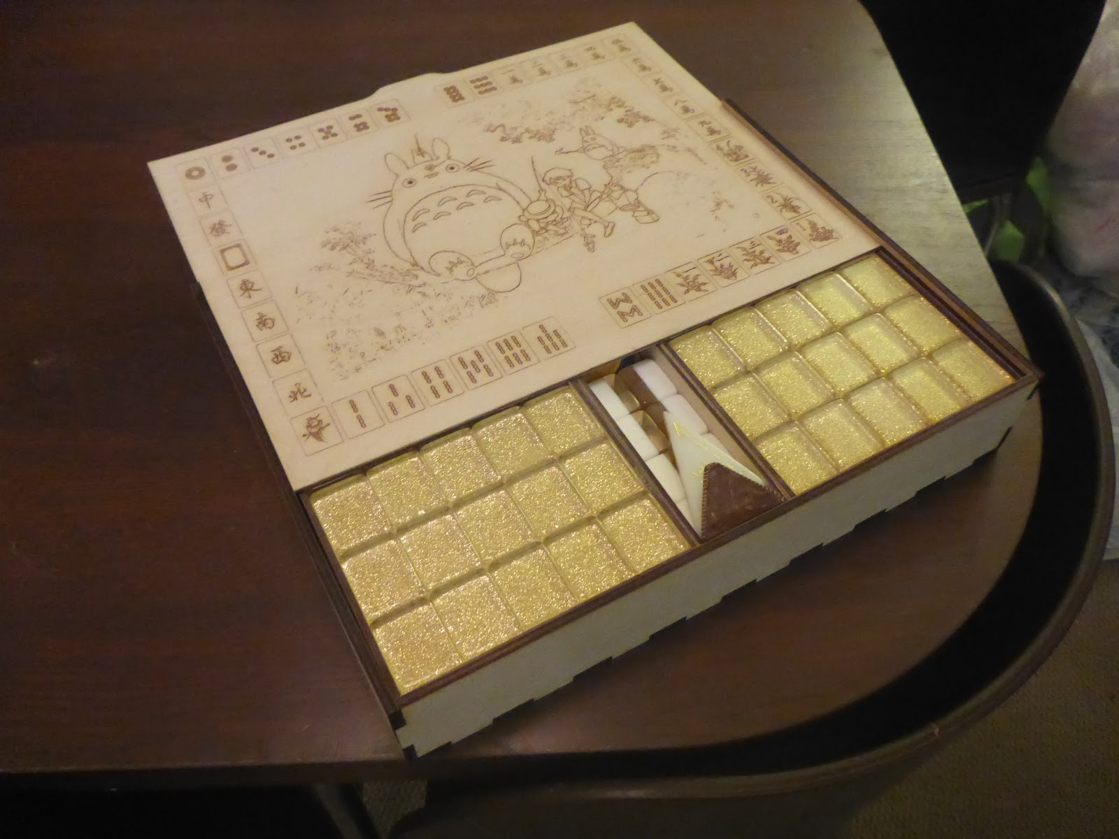
For some reason these nice Mahjong tiles come in a decomposing vinyl box, which smells horrific. So for my friend Hanh, we have a laser cut and etched box with trays, displaying iconic scenes from "My Neighbor Totoro". The build photos are somewhere, or nowhere (deleted?), but here's the final product.

Not seen: the center tray was the last to cut, since it went through about three iterations. It was too thick at times, and unlike the vinyl predecessor, this wooden case has exact dimensions to prevent rattling around.


All large surfaces, except for the backside of the lid, have rasterized images that were edited to look good when lasered. The lid tile design was part of the Totoro image, so it took the longest to etch. To lessen the processing time, I ran some tests at different settings to find the best quality to speed ratio. Once finished, I gave everything a good power sanding to make the wood less grippy, followed by a light spray of matte acrylic to reduce moisture damage in the future. The trays have holes for pushing tiles out, otherwise you'd have to dump them all over. I purchased the fake leather handle and matched the thin center tray with laser cut fake leather handles with golden thread accents. Oh here, I found an image:


Special thanks to Loi for taking photos of the box.

One more...