Thursday, March 19, 2020

Fila-buster Saga

 Ok...
The Problem:

1.75mm filament needs to be cut into pellets for a friend's manufacturing processes. I won't be addressing the "Why" in this post.

The History:

     Years ago I built a little machine that would save human time by cutting pellets. Here's a photo of the machine in action. 


     Considering it's been in operation for so long, the concept is solid enough to run with. It's essentially a stepper motor pushing filament through a filament sized hole. Another motor maneuvers a steel arm down to cut it. It does this about once a second, and currently runs a little faster since upgrading the stepper driver to a Gecko 201x, but that's really only a Band-aide on a rather large stream of issues. 

     The amount of pellets in the photo is about 2-3 hours of work. Not only that, but as you can also see, they are statically charged. So not only is it days to get enough material for any real use, it's sticky and hard to handle. 


Design Alterations:

     Over the past year or so I've come up with a few ideas I thought were worth looking into. They all have a few things in common; they're supposed to run fast, they're small designs in keeping with the old design. Lets run down the list.


     Here's the design we've seen, with annotations in case it gets confusing. As it stands, maintaining the electronics is sketchy, and the computer/driver/wires are all stuffed in that little box under the feed motor. It gets warm in there. How it works is there's a little button on top that gets pushed in by the cutter bar, which indicates to the logic when to push more filament through. This is not a flexible system, especially considering part wear. The linkage system connecting the motor to the cutting bar is not very lined up, and is either too tight or too loose, causing partially cut pellets and a loud squeal because of the motor current chopping attributes. It's been modded to use a fancy stepper driver which will get it running for another few years, but it's currently a huge bottleneck if the end user needs enough material within the next hour. 


     This design was always in the back of my mind. It's very similar to the v1 design, but with a different power train for maximizing the cutting force and speed. It never made it into the prototyping stage because it lacked an increase in speed. 


     This design uses an electromagnet to force the cutting bar down. The idea is speed and force. The electromagnet was made, but thinking about it further kept me from pursuing this iteration. 


     Here's that electromagnet I was testing. I used an online calculator to figure out how many winds of which gauge I'd need.


     There was another design involving interlocking gear teeth , but it was absolutely inflexible with pellet size and screamed 'wearable parts'. The only reason it was considered is I had an old stick blender motor lying around. Can't beat raw AC power...which brings us to our next design.


The Solution (v2)

     This is a machine that solves a problem, right? It's got to run fast, no excuses. So let's replace that Nema 23 motor with a 1/2 hp motor, and let the feed motor run as fast as it can (reliably). 


     It's not exactly small anymore, let's call it medium. The plan is to give it all the features. The wearable parts are off the shelf, and it can accommodate changes in case the supplier of said part is no longer in business. Let's look at some more photos. 


     Using corrugated plastic as a footprint, I began figuring out where things should go. My plan is to have the high power stuff on the right, with 12v over on the left. I have no idea how this much electrical noise will affect my Arduino based circuitry, so I'm playing it safe. There's a noise filter right before the motor, so that should help protect other sensitive electronics on the grid. I didn't cheap out on the cutting blade coupler, and initial testing showed no worrisome vibrations. It's a 1,700 RPM continuous duty motor, so I think we're going to be okay. 

     Here's the (fancy) hardwood plywood that I use as a base. The motor still has grounding, however. It's 3/4 inch thick, which offers very little deflection. 


     After the metal plate is cut and assembled, I can begin final design of the feed motor and actually do some practical testing. 


      With the metal plate removed, here's the testing layout. The feed motor is sitting on the desk on the red plastic bracket. It was 3D printed in ABS and is beefy enough to take a beating. The funny white plastic object with wheels is my "Fila-meter". I did several iterations on this, some using compliant devices printed in ABS. It's designed to detect if the machine is receiving filament, and how much. I've already given my class an earful on that, so I don't feel it necessary to go on that tangent. The final version uses bearings, rubber coated surfaces, and metal bushings, so filament running through doesn't wear down the printed parts.


     For the circuitry, my first thought was to do a solder-trace protoboard like all my other projects. However, after watching an encouraging episode of EEVblog, I spent a few hours learning KiCad, and ordered my first PCB a few days later. The image to right is actually the second revision. It adds diodes to transistors, rework the traces, move some things around, and added a Bluetooth module. Bluetooth and the Arduino based boards are going to be daughter boards, so my board is simply a breakout for the sensors and power. Both the old and new versions of the board work well, so no problems there. If you're even remotely interested in PCB design, watch a KiCad tutorial. Turns out it's pretty easy and lots of fun. 


One thing, I wanted a large capacitor on the main power line to keep the logic running when the stepper driver is taking up all the juice. 47uf is probably way too small to do that job. However, it doesn't actually need it anyway, but everything was left as is.


     This is the final control board assembly. The connectors point up to maximize the footprint. They also allow the wires to screw to the terminals before plugging in for ease of maintenance. The modules are easily swap-able in case something happens (I'm not an EE after all).


Now that everything is figured out, it's time to build the case that covers everything. I used my laser cutter to make the guard and electronics box out of 3/16 acrylic. It's not the strongest material, and if this were any other application the box would be metal and grounded. 


Final build:

     At this point I tested everything again, added some extra safeties to the code, and built the app (MIT App Inventor) that will talk to the machine. Let's go over the features:


-Bluetooth to optionally receive warnings or simply check in on the progress. The machine is fully functional regardless of Bluetooth connection

-LED flashes depending on the error, and reports this error in plain text to the Bluetooth app (vibrates phone + alarm if something goes wrong)

-Immediately shut down if the blade guards are removed (two magnetic sensors on the blade guard)

-Immediately shut down if the lid is opened

-Immediately shut down if the vibration sensor trips (drops off a table, something falls on it, motor becomes unbalanced, human flailing, etc.)

-Immediately shut down if any of the sensor wires are cut 

-If any errors are present, the motor never turns on to begin with

-Internal resettable overheat fuse in the motor, resettable fuse on the side, and circuit breaker to prevent short circuits. If the relay welds to itself and doesn't shut down, the circuit breaker can be flipped off like a 30 amp light switch.

-Fila-meter to ensure filament is being processed in an expected way. If it's too short or stops detecting a feed altogether, the machine stops

-Hidden ion generator that pumps ionized air into the cutting chamber to neutralize static

-The switch that turns on the machine is isolated from the AC line, only 12v shock hazard if everything goes wrong 

-Operates 70-80 times faster than the first machine 

-Adjustable pellet size from 1-2.5mm via potentiometer.

Really, it's a machine designed to turn off.

Cheers


Monday, June 24, 2019

Drone Buddy Gimbal Controller


I decided to pull my drone out of the void. Since getting my 3-axis camera gimbal tuned and stable, it was destined to be mounted to the 5-foot, 8 propeller behemoth. Long story short, the landing gear was purchased and the mounting plate was custom made to connect it all together. Here's a photo with a test acrylic mount plate:

The acrylic plate is that white piece at the base of the landing gear pivot. I then landed on it and everything toppled over when it broke. I suspected this might happen. I learned nothing.


The pant/tilt movements of the camera and the landing gear retract were paired to the controller. This is great for multitaskers, because there's nothing more fun than steering a brick while trying to fiddle with a camera. I can only assume the GPS will give out when I least suspect it, and I'll need full control over a safe landing.

Queue coworker: "You should get another remote for the camera and we can fly that thing."

That's great, but I'm not going to buy a second remote. That's too easy and I still learn nothing. For the record, that would be the best and most professional method to deal with this problem.

Anyways here's what I'm doing.


After a few iterations, I made (3D print, laser, Plasti Dip, etc) a nice little remote. It has an Ethernet port on the back that will interface with the 16 channel Taranis RC remote, allowing control by two people with the same transmitter. It will pan/tilt the camera, allow roll control, reset the gimbal, and enable/disable the gimbal motors. This way I don't have to land in order to fix resonant jitter issues. There's an extra potentiometer for expand-ability but mostly symmetry.

I've done all the recon and found the pots I'm using work well with the RC remote, it just needs a change in wiring harness to facilitate this. The drone will have a second receiver to accommodate the added channels for resetting the gimbal and roll control, which leads to the sane conclusion of just get a second remote and don't risk making a mess of things. But we're all about learning on this blog.


Shout out to Vetco of Bellevue for the JST PH connectors. They're not free but hey they exist.Stay tuned...


Tuesday, May 14, 2019

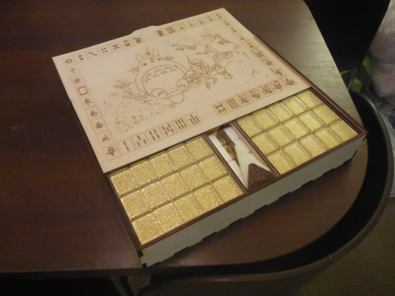
Totoro Mahjong Box


For some reason these nice Mahjong tiles come in a decomposing vinyl box, which smells horrific. So for my friend Hanh, we have a laser cut and etched box with trays, displaying iconic scenes from "My Neighbor Totoro". The build photos are somewhere, or nowhere (deleted?), but here's the final product.

Not seen: the center tray was the last to cut, since it went through about three iterations. It was too thick at times, and unlike the vinyl predecessor, this wooden case has exact dimensions to prevent rattling around.


All large surfaces, except for the backside of the lid, have rasterized images that were edited to look good when lasered. The lid tile design was part of the Totoro image, so it took the longest to etch. To lessen the processing time, I ran some tests at different settings to find the best quality to speed ratio. Once finished, I gave everything a good power sanding to make the wood less grippy, followed by a light spray of matte acrylic to reduce moisture damage in the future. The trays have holes for pushing tiles out, otherwise you'd have to dump them all over. I purchased the fake leather handle and matched the thin center tray with laser cut fake leather handles with golden thread accents. Oh here, I found an image:


Special thanks to Loi for taking photos of the box.

One more...


Sunday, February 10, 2019

Plotter Attachment for Laser Cutter

Long story short, I had an old inkjet printer. I've seen some DIY plotter machines made from old printers, so I thought, why not? how hard could it be

Data warning: ~76MB in GIFs on this post.

 Turns out, there's a reason to keep the old gantry inside the original printer case. The paper feeder can be out of alignment to the rollers, and it causes the paper to shift as it goes back and forth. Even well made plotters can suffer from alignment issues. Let's start with the first design: 


It's basically an enclosure for all the electronics and rolling mechanics. This took several iterations before I had all the dimensions where I wanted them. When I was happy, I started making the wood version.


 Partially assembled, I added the printer gantry. The electronics worked with the open source software I found (some GRBL controller for Arduino). Confident it would work, I put a piece of paper in. The result was paper that would rotate slightly with each back and forth movement. I thought a slight design change would fix it, but I also knew this would always be a problem, no matter how fine I tune it.


So, it sank into the swamp.

I decided a standalone plotter was too much effort, since my laser cutter already has an XY transit system I could use. After some fiddling around, I found some pins on the control board that indicates the laser firing, even when the laser power is off. This was my trigger for a solenoid. The idea was to use maybe one or two transistors, a relay, and some passive components for the entire system.


I didn't like how oddball the device was looking. It was unpredictable, sometimes the solenoid would get stuck, it was wobbly in places, got hot real fast. Sank into the swamp.

Next version involved the same nozzle clamp system as the last, but that's the only similarity besides the red color. It's Arduino controlled, so I can set exactly how far it moves, how much power it's getting, when it triggers, all the good stuff. 


The only problem is the device was also wobbly; the only thing keeping it level was the drive screw. At slow speeds it was alright. Unfortunately, I have aspirations, so this too sank into the swamp.

There was another...

This final version was designed to be much beefier. I added rails to keep the whole system rock solid, while adding features that didn't impact stability. This one has it all. It's got a rotating head that can be adjusted for calligraphy pens or simply drawing with a slanted pencil. I've also added a set of rails so the tool can sit on top of the material, not be forced to puncture it. This way I can roughly set the height of the tool, and it'll still work just fine. 


Here's a test of the up/down action, tripped by the laser trigger. All the electronics were in the design phase, so breadboard and Arduino 2560 still in the picture.

 Here's the final shape based on my redesign. Nice big knob for changing out tools. I'd like to say the hardware cost $3, but this is Seattle. Each of those two collars by the motor cost over $3 each. Total of about $25, not including the motor and hardware I already had. No idea where everyone is getting their $3 hardware from, but I guess I'm supporting my local businesses this way.
 

Shot of the attachment on the laser.


I have a bag of blank through-hole circuit boards, so I designed the electronics around that. Using an Adafruit Metro Mini as the brains and a Pololu stepper driver for the brawn.


Solder traces are not fun with a blunt tip. 


 Here's how I tied everything into the exiting circuitry of the laser. The power supply gives 24 volts and about 2.5 amps. I figured it could spare an extra half amp. Worst case, I know where to find a new one. The TTL trigger from the M2 Nano board needed a 100,000 ohm resistor to block any rouge signals. The 5v for the logic was supplied with a small transformer I installed to the right of the power line filter, out of frame. I can tap into that if I add anything else later on. The custom board is currently mounted neatly next to the power supply. Paired wires are twisted and hidden within the rail. I promise it doesn't look this messy right now.


After painstakingly threading all the wires through the drag chains, I added a connector for quickly releasing the plotter attachment. I'll have to add a switch for deactivating the electronics when not in use. Everything works. I'll want to avoid drawings where the stepper is moving constantly because of heat issues, but I can always run it slower. There's a "test" button I can use to raise the pen higher than during normal operation, so I can change out tooling easily.


"But the fourth one stayed up. And that’s what you’re going to get, Son, the strongest castle in all of England."
          -King of Swamp Castle


Weird code for reference:


const int testPin = 7;
const int limitPin = 6;
const int inputPin = 5;
const int motordir = 3;
const int motorstep = 4;
const int motoroff = 10;

int test = LOW;
int limit = LOW;
int input = LOW;

int var_busyup = 0; //busy 1 or idle 0
int var_busydown = 0; //busy 1 or idle 0
int var_direction = 0; //down 0 or up 1 direction
int var_running = 0; //indicates that it's in running mode, for when listening to the input
int var_updistance = 0; //variable to control the up travel distance depending on mode


void setup() {

pinMode(testPin, INPUT);
pinMode(limitPin, INPUT);
pinMode(inputPin, INPUT);
pinMode(motordir, OUTPUT);
pinMode(motorstep, OUTPUT);
pinMode(motoroff, OUTPUT);

digitalWrite(motoroff, HIGH);

delay(1000);
}

void loop() {
 
test = digitalRead(testPin);
limit = digitalRead(limitPin);
input = digitalRead(inputPin);


digitalWrite(motoroff, HIGH);

if (input == LOW){
  var_running = 1;
}

if (test == HIGH){
  var_running = 0;
}

if (((test == HIGH) && (limit == LOW) && (var_busyup == 0)) || ((input == LOW) && (limit == LOW) && (var_running == 1) && (var_busyup == 0))){
  var_busydown = 1;
  for (int x = 0; x <= 150; x++){
    digitalWrite(motoroff, LOW);
    delay(1);
    digitalWrite(motordir, LOW);
    digitalWrite(motorstep, HIGH);
    delay(5);
    digitalWrite(motorstep,LOW);
    limit = digitalRead(limitPin);
    digitalWrite(motoroff, HIGH);
    if (limit == HIGH){
      break;
      }
    } 
  }
var_busyup = 0;
limit = digitalRead(limitPin);
input = digitalRead(inputPin);

if (((test == HIGH) && (limit == HIGH) && (var_busydown == 0)) || ((input == HIGH) && (limit == HIGH) && (var_busydown == 0) && (var_running == 1))){
  var_busyup = 1;
  if (var_running == 1){
    var_updistance = 10;
  }
  if (var_running == 0){
    var_updistance = 90;
  }
  digitalWrite(motoroff, LOW);
  for (int y =0; y <= var_updistance; y++){
    digitalWrite(motoroff, LOW);
    delay(1);
    digitalWrite(motordir, HIGH);
    digitalWrite(motorstep, HIGH);
    delay(5);
    digitalWrite(motorstep,LOW);
    test = digitalRead(testPin);
    input = digitalRead(inputPin);
    digitalWrite(motoroff, HIGH);
    if (input == LOW){
      break;
    }
  }
}

var_busydown = 0;


}

Tuesday, January 22, 2019

Laser Dump and a Print

The laser made easy work of Christmas gifts for family and friends. These first ones have the family crest engraved on some glasses. You can see the super sculpey being put to good use, propping up the glass. The design was etched using a low power setting, rasterizing each line. The curvature wasn't too bad, so I didn't have to use the rotary axis for these. Just had to make sure they were perpendicular to the laser travel and level-ish. Pro tip, etching glass with a laser doesn't give off smoke, but it's important to keep the ventilation system running to suck up those microscopic glass particles. 


Here are a couple white elephant coasters for the gift exchange with friends. My partner helped draw the geometric shapes, while I finished it off in Inkscape to create the negative space for Totoro. The eyes, nose, and belly pattern were rasterized, the rest vectors for speed. It's difficult to clean out the tiny charred gaps with alcohol, but a coating of matte acrylic helps cover it up and prevent moisture from damaging the wood when in use.


 Some Alien themed coasters for my brothers. The middle one is actually Ripley holding Jones, the cat. Didn't turn out very well. Rasterizing these things always takes way too much time.


Got to use the rotary axis on a glass soda water bottle. The glass is full of distortions, which means the design is difficult to see. I also found out the motor was wired backward, causing the design to flip. Fortunately with this design, you can't tell. I've since fixed the issue. You can see how easy it is to set up. Just plug in and flip the switch. I'm currently building a plotter attachment that will involve more holes in the side of the case. 


Tiny antlion guard from Half-life 2, about 1.5 inches tall and painted. Printed this with my new Wanhao D7. It's quite different than the Pegasus Touch, but I've learned the quirks. Like, using the supplied flash drive is a bad idea and freezes the print mid way, and using a power line filter and ferrite cores are important so turning on the laundry machines don't crash a print. Kinda important. This is exactly why I want an oscilloscope, to confirm I'm not crazy. Love the printer though.


Monday, September 10, 2018

Laser Cutter - Rotary Axis

 For my previously mentioned laser cutter. I made a rotary axis that will be hooked up soon. I made sure to use a similarly sized motor to the one I'll be stealing power from on the Y axis, so I don't have to mess with the current. It will use a 2 position 4 way switch so I can change which motor gets the power. Just plug, and switch! The construction is very rigid with epoxy everywhere. I have attachments planned for tilting, live center, and steady rest. I'm also working on some way to protect the wood in case a stray laser attacks the tool.


DIY Laser Fume Extractor

 After purchasing a hobby laser cutter as any DIYer should, I quickly realized the fumes pumping out the window would be a problem. When the gas leaves the building, air must replace it, or it'll get sucked back in through any cracks. An open window in the bedroom helps. However, should any vapors return, I'd like them to be made harmless (and odorless). To mitigate this, I researched solutions and spent weeks designing my own. It must fit in the tight space under the laser cutter, be easy to open for filter replacement, and have quality parts.


 The construction is plywood screwed together, with silicon at all corners. The design is such that any leaks simply pull additional air in. So there's no risk of leaking gasses where it shouldn't. The worst* that can happen is the gas isn't filtered completely, and still gets pumped outside.


There are perfectly cut blocks slid into place over each component. This acts as a barrier to keep dirty air moving through the filters, and is removable for maintenance. Each loose part is lined with neoprene or window stripping. The perfect fit is because I also modeled this entire setup in 3D.


The finished product does a fine job, and isn't loud at all. Each of the filter and fan components is rated for around 250 cubic feet per minute capacity. Since the fan is at the end of the filter, it pulls in the walls of the box, creating an even better seal. No, that isn't a car engine filter attached to the fan. It's a HEPA filter, making sure any smoke or carbon is filtered out before running through the fan. My fancy test was lighting and blowing out a candle to see where the smoke pulled into the box. No leaks! At least not externally. Putting a scented candle at the inlet and my nose near the end yielded no odors, so it seems to be working. The purpose of this was not to go cheap, although it definitely saved money over any plug and play option.


Known downsides are the cost of filter parts. They weren't crazy, but there are other ways. The inlet being so close to the carbon filter is also an issue. It may develop preferred paths, lessening the filter ability over time. I can rotate the filter over time to help with this, or stick a piece of paper over the closest section of filter to diffuse the gasses around more, at the expense of a little suction. Cheers!